
Wire Rope Fatigue Cracks and Rail Surface Rolling Fatigue Cracks – Different Application but Similar Mechanisms
- Thomas R. Hay, Ph.D., P.E
- Mar 6
- 5 min read
Steel wire rope used in industrial and recreational applications are manipulated through sheaves and drums. The wire rope bearing surface hardens and beyond a certain point, fatigue cracks will initiate. Under optimal conditions, the wire rope bearing surface will wear at a rate faster than the crack initiation rate. Similarly, steel railroad surfaces develop rolling contact fatigue cracks over time and if the crack propagation rate exceeds rail surface wear rate, small fatigue cracks may propagate into larger transverse defects. This article explores some of the similarities between wire rope and railroad running surface wear, fatigue crack formation, and non-destructive testing methods for wire rope.
Wire Rope and Rail Surface Hardening
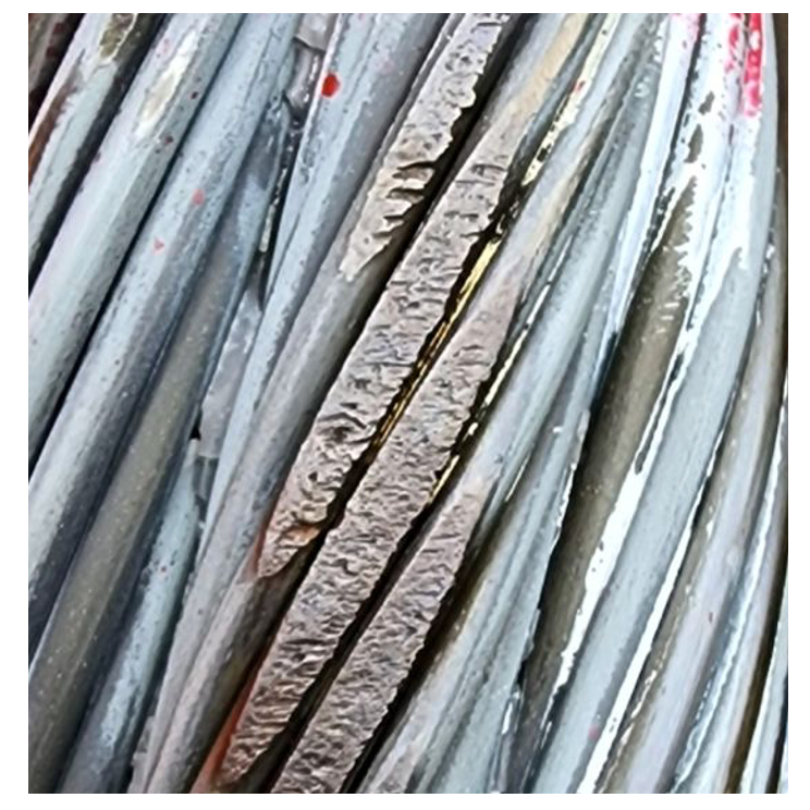
The contact surfaces between a wire rope sheave or drum, in combination with bending stresses, are the main initiators of wire rope fatigue cracks. Environmental factors like temperature and moisture may accelerate defect formation if left unmitigated. Newly installed wire rope will make point line contact with the drum surface but over time the bearing surface will increase due to tension, compaction, and wear. Continued wear will cause diameter reduction resulting in less surface contact leading to higher localized stresses. These stresses will eventually cause fatigue cracks which may lead to wire breaks. If the wear rate exceeds the crack initiation rate, the mechanism is mitigated until the wire rope diameter decreases beyond an acceptable tolerance.
The surface hardening, rolling contact fatigue crack (RCF) and wear phenomena in railroad running surfaces are similarly described. Rail wear acts in opposition to RCFs as it eliminates top surface material in which surface cracks may have initiated. Where the surface cracks are entirely contained in the work hardened layer, and removed by wear, this mechanism abates further propagation and more serious transverse defect formation.
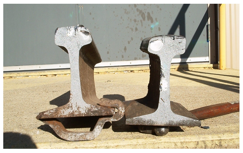
Table 1: Comparison of wire rope and rail fatigue crack influencers
Factor | Wire Rope Fatigue | Rolling Contact Fatigue (RCF) in Rails |
Primary Stress Type | Tensile, bending, and contact stress from repeated flexing and tension | Compressive and shear stress from wheel loads |
Material Loss | Diameter reduction from wear and corrosion | Surface plastic deformation, shelling, and spalling |
Failure Mode | Broken wires, internal strand fractures, or complete rope failure | Surface cracks growing into railhead fractures or rail breakage |
Load Transfer | Load shifts to remaining wires as individual wires break | Load redistribution to other sections of the rail, but eventual track failure if cracks grow |
Wire Rope Break Detection
Wire rope fatigue cracks are difficult to detect due to their small footprint and wire rope inspection frequency. A wire break caused by a fatigue crack or other wire diameter reduction mechanisms are typically the inspection goal along with diameter, or cross-sectional area, reduction. Magnetic flux leakage (MFL) testing of wire rope is the most used non-destructive testing (NDT) technique to detect wire breaks and diameter reduction, also referred to as local faults (LF) and loss of metallic area (LMA).
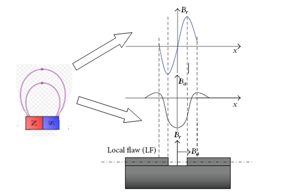
Detection of wire rope breaks and cross-sectional area loss using MFL technology starts by understanding the magnetic field generated by a wire break or discrete loss in outside diameter. Like the magnetic flux leakage field generated by pitting, generalized corrosion and cracking on the ID of a pipe [1] the MFL field developed around a wire break also generates a 3-D field with Bx, By, and Bz components. The Bx and Bz fields are also referred to as the axial and radial magnetic field components and are shown below in Figure 3 [2]. Consider that a wire break creates a small dipole with the resultant magnetic field shown on the left [3]. The radial and axial components of this field are shown on the right hand side. The radial magnetic field is very strong towards the edge of the wire break gap. Conversely, the axial magnetic field peaks towards the center of the wire break gap and is comparably small towards the start and end of the wire break. The axial and radial magnetic flux leakage field are the input into the selected inductive or hall sensors used for local faults and loss of metallic area sensors.
For a given magnetic flux leakage field radial component, the voltage output from an inductive sensor is calculated using the following relationship [4]

Where,
E – voltage output from inductive sensor
k – sensor coefficient or sensitivity
v – speed wire rope passing through the sensor
dBr/dx – Rate of change or slope of Bx across wire break
Some important observations regarding the Bz radial inductive coil sensor include: While the radial magnetic flux leakage component is 0 at the mid-point of the wire break, the output from the inductive coil is maximum, the rate of change of Bz is maximum at mid-point for small wire breaks, and finally the inductive coil response is dependent on wire rope speed.
For a given magnetic flux leakage field axial component, the voltage output from an Hall sensor is calculated using the following relationship [5].

Where,
E – voltage output from inductive sensor
k – sensor coefficient or sensitivity
Ba – Axial component of magnetic flux leakage field.
Some important observations regarding Ba axial component Hall sensor include: The axial magnetic field increases in intensity from the wire break to the mid-point then decreases, in contrast to the LF inductive Bz sensor the voltage output matches the magnetic field shape, and The Hall sensor voltage output is proportional to the magnetic field and dependent on the sensitivity k, and the output voltage is independent of rope speed.
A comparison of inductive sensor versus Hall sensor for output to radial and axial magnetic flux leakage field is shown below in Figure 4. The top MFL data was generated from a local fault or wire rope break. The radial MFL component was detected using the inductive coil sensor. The bottom MFL data was generated from loss of metallic area (LMW). The axial MFL component was detected using the Hall sensor.
Summary
Fatigue cracks form in ductile steel service application and may be partially mitigated if the wear rates exceed the crack propagation rates. Examples include wire rope fatigue due to bending stresses over sheaves and/or drums and rail surface hardening and rolling contact fatigue crack initiation. Magnetic flux leakage technology is used in the wire rope testing industry to detect wire breaks and loss of metallic area. MFL detection technology uses both inductive and Hall sensors to detect local faults and LMA. The resultant magnetic field, radial and axial components were presented in this article. MFL inductive and Hall sensor detection of these components was discussed connecting the magnetic flux leakage patterns to sensor output.
References
Shi Y, Zhang C, Li R, Cai M, Jia G. Theory and Application of Magnetic Flux Leakage Pipeline Detection. Sensors (Basel). 2015 Dec 10;15(12):31036-55. doi: 10.3390/s151229845. PMID: 26690435; PMCID: PMC4721765.
Xiucheng, Liu, Yujue, Wang, Bin, Wu, Zhen, Gao, Cunfu, He, Design of Tunnel Magnetoresistive-Based Circular MFL Sensor Array for the Detection of Flaws in Steel Wire Rope, Journal of Sensors, 2016, 6198065, 8 pages, 2016. https://doi.org/10.1155/2016/6198065
Qu Y, Zhang H, Zhao R, Liao L, Zhou Y. Research on the Method of Predicting Corrosion width of Cables Based on the Spontaneous Magnetic Flux Leakage. Materials (Basel). 2019 Jul 4;12(13):2154. doi: 10.3390/ma12132154. PMID: 31277467; PMCID: PMC6650906.
E. Kalwa, K. Piekarski, Design of Hall-effect sensors for magnetic testing of steel ropes, NDT International, Volume 20, Issue 5, 1987, Pages 295-301,
E. Kalwa, K. Piekarski, Design of inductive sensors for magnetic testing of steel ropes, NDT International, Volume 20, Issue 6, 1987, Pages 347-353,
Comments